1. Analog signal input(Universal input)
The recorder is designed with a maximum of 32 channels of universal signal input, which supports mV, V, mA, thermal resistance and thermocouple signals. The channel signal type is set by the input configuration, and the recorder automatically switches the corresponding acquisition circuit according to the signal type set by the configuration, and the signal acquisition period is 1 second
The channel can independently configure and set the unit, range, decimal point, adjustment, filtering, disconnection processing, small signal removal and other parameters.
2. Data recording and alarm, power-down and logs
The recorder sets the recording interval according to the system configuration to record the sampling data of the channel in real time, and the recording interval can be selected as 1 second, 2 seconds, 5 seconds, 10 seconds, 15 seconds, 30 seconds, 1 minute, 2 minutes, 5 minutes, 10 minutes, 30 minutes and 1 hour. The internal memory of the recorder is 64MB, which can store 900,000 records, and the recording interval of 32 channels is 1 second for 10 days. If the number of channels is reduced, the recording time will increase accordingly, and the recording mode is dynamic cycle covering storage. At the same time, the recorder records the channel alarm, instrument power failure and operation log information generated during operation, with 256 records each, and the recording mode is cyclic overwrite storage.
3. Display of data, curves and records
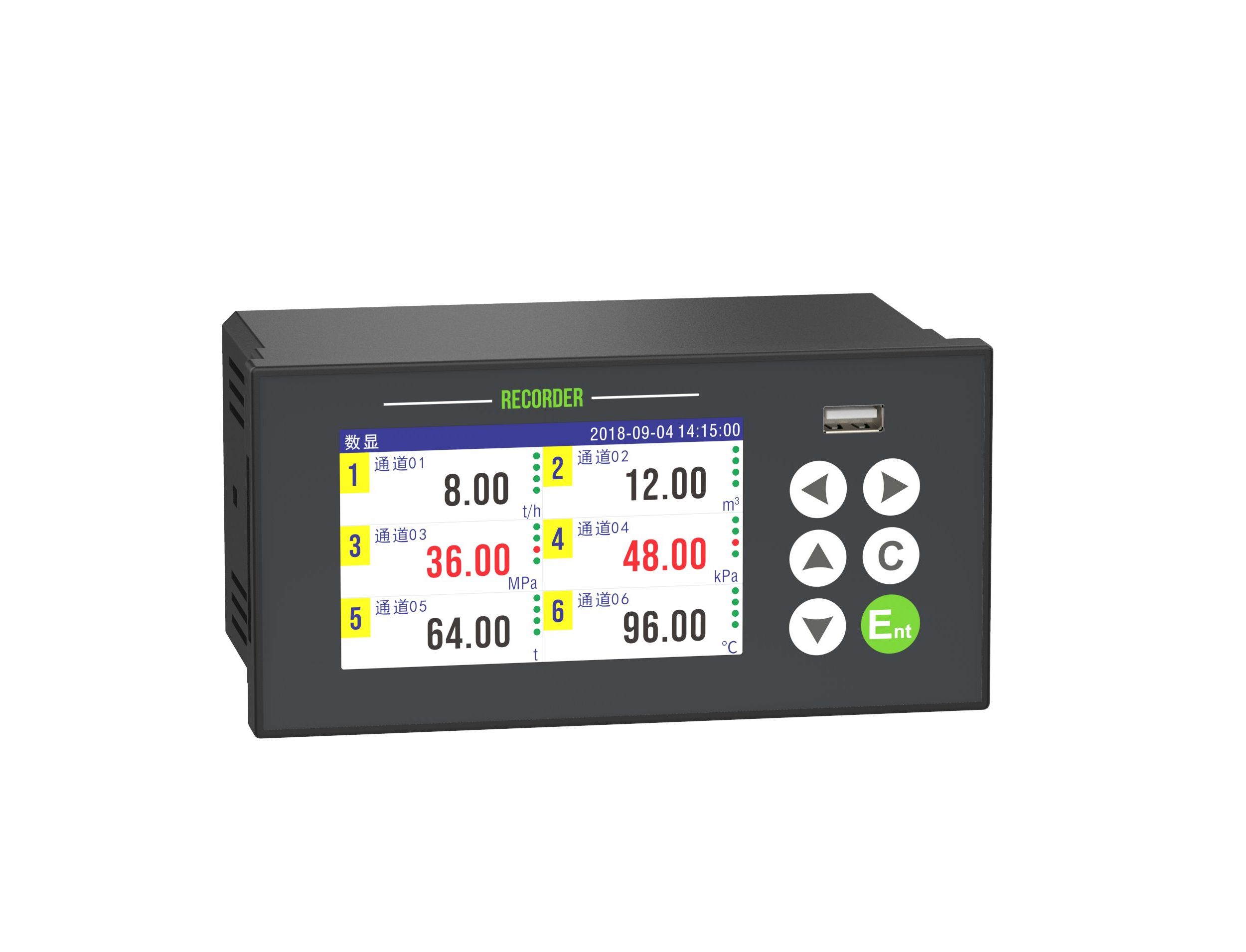
The recorder adopts a 7-inch high-definition touch color LCD screen with a resolution of 800*480 pixels. The recorder is designed with a variety of data display and viewing modes such as digital display, bar chart, real-time curve and dashboard, and can view historical data such as historical curve, alarm list, power failure record and operation log. The recorder is equipped with Chinese-English bilingual system, which can be switched and used independently.
4. Alarm relay output
The recorder is designed with at most 16 alarm relay outputs, and the relay type is normally open. By setting the alarm configuration, you can arbitrarily specify the connection between relay contacts and channels, and you can set four alarm types: high alarm, low alarm, high alarm and low alarm, and you can set alarm back difference and relay delay parameters.
5. 24VDC Output
The recorder is equipped with 2-loop 24VDC power outputs, which are used to power the sensor, and can directly drive the two-wire sensor. The current loop is connected in series with the input channel of the recorder.
6. RS485 with Modbus RTU
The recorder is equipped with one RS485 communication interface, adopts standard Modbus RTU communication protocol, supports real-time data of channels, alarm status of channels and other data.
7. Ethernet with Modbus TCP
Ethernet communication interface can be selected for recording, and standard Modbus TCP/IP protocol is adopted to realize external data communication and transmission, and support real-time channel data, channel alarm status and other data.
8. RS485 data acquisition
The recorder can be equipped with RS485 data acquisition interface, and the instrument data of other lower computers can be read as channel values through standard Modbus RTU protocol.
9. Formula operation function
The recorder supports users to independently configure mathematical operation formulas and realize advanced data calculation between channels.
10. 4-20mA Output
The recorder can be equipped with up to 8 channels of 4-20mA transmission and output functions, and the transmission relationship between output channels and input channels can be configured through output configuration settings.
11. Micro-printer port
Optional micro printer port, automatic real-time printing of data and curves, and manual printing of historical data and curves.
12. USB data backup
The recorder is equipped with USB2.0 interface, which manually exports historical data to USB stick through USB interface and automatically regularly backup historical data.
13. Configuration import and firmware updates
Support for importing and exporting configuration parameters and update instrument firmware through USB interface.
14. Flow accumulation (no TP compensation)
The recorder supports the channel flow accumulation, and does not have the temperature and pressure compensation function.
15. Vacuum algorithm
The recorder supports the channel vacuum algorithm, and combines the output signal with the vacuum meter to calculate, store and display the data in the form of vacuum.
16. Maser computer data management software
The recorder provides the data management software, supports the data export of superior disk, and supports the real-time monitoring data of single machine. Support the curve and the data display mode, you can export the EXCEL report.
| Item | Description |
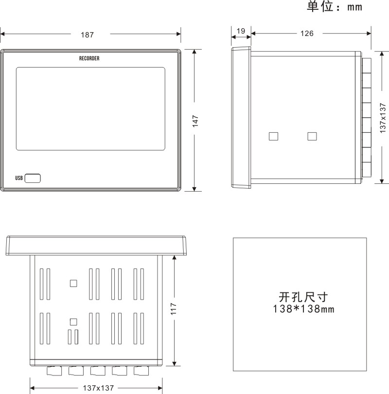
| Dimension | 187*147*145mm(WHD), Mounting hole 138*138mm |
| Screen | 7-inch color touch LCD, 800*480px resolution |
| Channel* | Up to 32 universal analog inputs |
| Accuracy | 0.2%F.S. |
| Sampling period | 1 second |
| Alarm* | Up to 16 normally open relays, 250VAC 3A, 30VDC 3A (resistive load) |
| Transmitter* | Up to 8 transmission outputs, 4-20mA with load ≤750Ω, Accuracy 0.2% |
| 24VDC output | 2 24VDC±10% outputs , total output current ≤120mA |
| RS485 | RS485 communication interface, standard Modbus RTU protocol |
| Ethernet* | 10/100Base-T RJ45 port, standard Modbus TCP protocol (≤3 connections) |
| RS485* | 1 RS485 acquisition interface, standard Modbus RTU protocol. |
| USB | USB2.0, supporting 32G USB stick |
| Micro printer* | TTL micro printer interface |
| Power supply | 100-240VAC 50Hz / DC 24VDC±10% (reverse protection) capacity ≤ 20W |
| Preheating time | 30 minutes |
| Work environment | Temperature: -10~60℃ Humidity: 0~85%RH (no condensation) |
| EFT | Power supply 2000V, Signal 1000V. |
| ESD | Contact discharge 4000V; Gap discharge 8000V. |
| Withstand Voltage | AC220V power supply: 1500V between terminal and ground DC24V power supply: 500V between terminal and ground 1000V between isolated terminals and terminals |
| Insulation Resistance | AC220V power supply: DC test voltage 500V 20MΩ DC24V power supply: DC test voltage 100V5MΩ |
| Recording interval | 1 sec, 2 sec, 5 sec, 10 sec, 15 sec, 30 sec, 1 min, 2 min, 5 min, 10 min, 30 m, 1 h |
| Data memory | 64MB memory, 900k records |
| Recording Duration | 32-channel with 1-second recording interval, recording for 10 days, and dynamic cyclic overwrite storage. |
| Other records | There are 256 alarm lists, power switch records, and operation logs, which are stored circularly. |
| Installation | Panel mounting indoor , IP65 protection level for panel |
| Net Weight | 1100 grams |
[Note] * is optional
| Category | Signals | Scale | Accuracy/25C |
| Current mA | 4-20mA | 4.00~20.00mA | ±0.2% |
| 4-20mA sqrt | 4.00~20.00mA | ±0.2% | |
| 0-20mA | 0.00~20.00mA | ±0.2% | |
| 0-10mA | 0.00~10.00mA | ±0.2% | |
| Voltage mV | 20mV | 0.00~20.00mV | ±0.2% |
| 100mV | 0.00~100.00mV | ±0.2% | |
| Voltage V | 0-5V | 0.000~5.000V | ±0.2% |
| 1-5V | 1.000~5.000V | ±0.2% | |
| 0-10V | 0.00~10.00V | ±0.2% | |
| TC | K | -200~1372℃ | ±2℃ |
| S | -50~1768℃ | ±3℃ | |
| B | 250~500℃ | ±5℃ | |
| 500~1820℃ | ±3℃ | ||
| J | -210~1000℃ | ±2℃ | |
| R | -50~100℃ | ±4℃ | |
| 100~1768℃ | ±3℃ | ||
| N | -200~1300℃ | ±3℃ | |
| T | -200~400℃ | ±2℃ | |
| E | -200~1000℃ | ±2℃ | |
| WRe3-25 | 0~2315℃ | ±5℃ | |
| WRe5-26 | 0~2310℃ | ±5℃ | |
| F1 | 700~2000℃ | ±2℃ | |
| F2 | 700~2000℃ | ±2℃ | |
| RTD | Pt100 | -200.0~650.0℃ | ±0.5℃ |
| Cu50 | -50.0~140.0℃ | ±0.5℃ | |
| Cu53 | -50.0~150.0℃ | ±0.5℃ | |
| Cu100 | -50.0~150.0℃ | ±0.5℃ | |
| Fr | Fr | 0~10000Hz | 1Hz |
| PLR30 | [ ] | [ ] | [ ] | [ ] | [ ] | [ ] | [ ] | [ ] | [ ] | [ ] | [ ] | 触摸彩屏无纸记录仪(隔离型) |
| 模拟输入 | 01 | 1通道 | ||||||||||
| 02 | 2通道 | |||||||||||
| \ | 3-31通道 | |||||||||||
| 32 | 32通道 | |||||||||||
| 虚拟通道 | ||||||||||||
| V1 | 1路虚拟通道 | |||||||||||
| V2 | 2路虚拟通道 | |||||||||||
| \ | 3-31路虚拟通道 | |||||||||||
| V32 | 32路虚拟通道 | |||||||||||
| 报警 继电器 | R2 | 2路报警:标配 | ||||||||||
| R4 | 4路报警 | |||||||||||
| \ | 6/8/12/14路报警 | |||||||||||
| R16 | 16路报警 | |||||||||||
| 变送输出 | ||||||||||||
| B1 | 1路变送 | |||||||||||
| B2 | 2路变送 | |||||||||||
| \ | 3-7路变送 | |||||||||||
| B8 | 8路变送 | |||||||||||
| 通讯/配电 | CP | RS485通讯;2路配电:标配 | ||||||||||
| USB | U | USB | ||||||||||
| U1 | USB接口含优盘 | |||||||||||
| 微打 | ||||||||||||
| Y | 微型打印机接口 | |||||||||||
| 485采集 | ||||||||||||
| T | RS485数据采集接口 | |||||||||||
| 以太网通讯 | ||||||||||||
| W | 以太网通讯接口 | |||||||||||
| 电源 | 交流220V电源 | |||||||||||
| D | 直流24V电源 | |||||||||||
| 语言 | ||||||||||||
| E | 英文版 | |||||||||||
| 备注: | 1. Standard configuration is 2-channel alarm, USB, RS485 communication, 2-channel power distribution; standard configuration is virtual computing function. 2. The recorder has a total of 4 slots and can be configured with 4 boards. Board types: 8-channel input board, 16-channel alarm board, 8-channel transmission board; General configuration: 24 inputs + 16 alarms (i.e. 3 input boards + 1 alarm board). 3. Input up to 32 channels, occupies 4 slots, and can no longer configure alarms and transmissions. 4. Configure the alarm board and output board, which will occupy the slot and reduce the input channel accordingly. The micro printer interface and the RS485 data collection interface cannot coexist. 6. No more than 32 virtual channels + analog channels. | |||||||||||


